Backlash Compensation
Every drive train has a little play. When an axis reverses, the motor turns before the table does, and the control believes it has moved when it has not yet.
On a part that shows up as a step at every direction change: a circle that comes out with flats where the axes swap direction, a bore that measures round on one side and not the other, a finish pass that leaves a witness line down the middle of a wall.
How the correction works
Section titled “How the correction works”The control keeps, per axis, the direction the drive train is currently loaded in, the reference flank. The nut is up against one side of the thread, and while the axis keeps moving that way the command needs no correction at all.
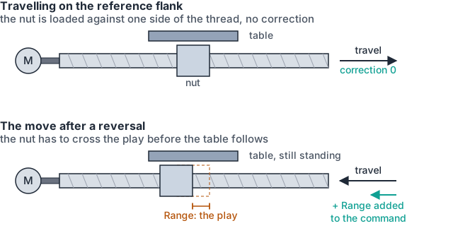
When the axis is asked to move the other way, the nut has to cross the play before the table follows. So for as long as the axis is travelling against the reference flank, the control adds the lash to the position it commands, in the direction of travel. The drive turns that much further, the table ends up where the program asked, and the correction comes back off again the moment the axis returns to the reference direction.
The correction is added to the command sent to the drive and taken back out of the position reported back. The readout does not jump when lash is taken up, and the following-error monitor is not fed a discrepancy that is not really there.
The reference flank has to be known first
Section titled “The reference flank has to be known first”A machine that has just powered on does not know which side of the play it is sitting on, and a wrong guess applies the correction backwards.
- Homing settles it. The final approach direction of the homing move becomes the
reference flank. Compensation is suppressed for the whole of the homing sequence and
armed again when the axis reaches
CALIBRATED, so nothing is corrected while the reference itself is being established. - Before that, the axis has to earn it. With no flank known, the control watches how far the axis has travelled in one consistent direction. Once that exceeds the configured lash, the play is certainly taken up, and that direction becomes the reference flank. No correction is applied until then.
- Losing the reference loses the flank. An axis that goes back to not-calibrated drops it and starts over.
The values
Section titled “The values”Per axis, on the axis’s Parameter tab, under Backlash Compensation.
| Field | What to enter | Unit |
|---|---|---|
Enable | whether the correction is applied at all | none |
Range | the axis’s measured lost motion | mm |
Compensation Ramp Cycles | how many control cycles the take-up is spread over | cycles |
Range at zero applies nothing, whatever Enable says.
Spreading the take-up
Section titled “Spreading the take-up”Travelling along a compensation curve is continuous and needs no smoothing. A reversal is not: it swaps one curve for another, and written straight to the drive that step excites the machine, giving a bump in following error and, on a stiff machine, an audible knock.
Compensation Ramp Cycles spreads that step. The weight is flat at both ends, so the
injected velocity starts and stops continuously instead of stepping, and the count is
capped internally at the point where a longer ramp would start fighting standstill
monitoring.
At zero or one cycle the step is applied whole on the next cycle. That is the default, and it is a real choice rather than an omission: spreading the step buys smoothness at the cost of contour error smeared along the path travelled during the ramp. Which of the two is worse is a property of the machine, which is why the machine builder sets it.
Start with a few cycles. If the reversal is audible, or following error spikes at direction changes, spread it further.
The same field also spreads the reversal step of a bidirectional leadscrew table. One number covers both, because both are the same event.
Measuring it, rather than looking it up
Section titled “Measuring it, rather than looking it up”The number is not the ballscrew’s catalogue backlash. What the control has to take up is everything between the encoder and the tool: screw, nut, coupling, bearings, and the servo’s own response.
Run either cycle with backlash compensation disabled. With it enabled you measure what is left over after the correction, not the lash itself.
| Cycle | Needs | How it works |
|---|---|---|
O8520 | a touch probe with trigger edge set to both | approaches one rigid face, latches the trip going in and the reset coming out at the same contact point, and reports the difference. The ball radius and pre-travel cancel, so no stylus calibration is needed |
O8521 | a dial indicator | loads the flank with a long one-way approach, stops for you to zero the dial, reverses by a set step and stops again. The reading is the step minus the lash |
O8520 measures X, Y or Z, selected by parameter. O8521 is the X-axis cycle, for a
machine with no probe. Both leave their result in a persistent variable to be read off the
variable screen and typed into Range by hand. Neither writes the axis setting itself.
Measure at the feed the machine will work at. Lash measured by hand at creep speed is not what a cutting move sees.
What it does not fix
Section titled “What it does not fix”- Error along the screw. Pitch that varies with position is leadscrew compensation.
- Squareness and geometry across the working volume. That is volumetric compensation.
- A worn nut. Compensation hides lash from the position loop; it does not stop a loose drive train from chattering under load. If the number keeps growing, the machine needs a fitter, not a bigger number.
Where to go next
Section titled “Where to go next”- Leadscrew Compensation: the error that varies along the axis.
- Axes & Channels: the homing settings that decide the reference flank.