Leadscrew Compensation
A ballscrew is not perfect along its length. Pitch varies, the screw stretches under its own preload, mounting distorts it. So the axis reads 300.000 and is somewhere else, by an amount that depends on where it is.
That error is measured once with a laser interferometer and handed to the control as a table of corrections.
How the correction works
Section titled “How the correction works”The table maps a machine position to the deviation measured there. Delta is measured
minus commanded: an axis commanded to 300.000 where the laser reads 300.012 has a delta
of +0.012. To correct it the drive has to go the other way, so the control applies the
negated delta.
Between two measured points the correction is straight-line interpolated, through every point rather than fitted past them. A fitted curve would leave residual error at the very positions that were measured.
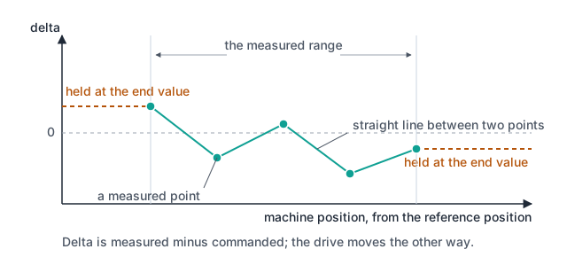
The points do not have to be evenly spaced. Each row carries its own position, so a table can be dense where the error moves quickly and sparse where the screw runs true, and an interferometer’s output can go in as it was measured rather than being resampled onto a fixed grid.
Outside the mapped range the correction is held at the end point’s value, not extrapolated. Past the last measured position the axis keeps the last correction it had and gets no worse and no better, which is why the table is measured over the travel the machine actually works in.
The correction is added to the command sent to the drive and taken back out of the position reported back, so nothing about it appears in the readout or in following error.
When it is armed
Section titled “When it is armed”Three things have to hold, and the correction is off unless all three do: the axis is
Enabled for it, the table has at least one point, and the axis is referenced.
The table is indexed in machine coordinates measured from the reference position. An unreferenced axis has no frame to look the correction up in, which is why the machine is referenced before it is measured, and why a changed home position invalidates the table.
One table or two
Section titled “One table or two”A screw does not repeat itself in both directions. Leave the ↓ column at zero and the
forward table answers both, and Direction Mode then reads Single table. Fill it in and
each direction gets its own curve, and Direction Mode reads Bidirectional.
Two tables are worth having when the error genuinely differs by approach. If it does not, a second column of near-identical numbers adds nothing and doubles what has to be re-measured later.
Where the difference is a constant offset rather than a shape, that is lash, and it belongs in backlash compensation instead.
A reversal on a bidirectional table swaps one curve for the other, which steps the drive
command. That step is spread over Compensation Ramp Cycles, the same field and the
same mechanism as the backlash take-up. Arming and
disarming the compensation are spread the same way. Travelling along the table is
continuous and needs no smoothing at all.
The table
Section titled “The table”Per axis, on the axis’s Leadscrew tab.
| Column | What to enter | Unit |
|---|---|---|
Position (mm) | a machine coordinate, measured from the reference position | mm |
Delta ↑ (mm) | the deviation there, approaching from one direction | mm |
Delta ↓ (mm) | the deviation approaching from the other | mm |
The arrows are the ISO 230-2 approach direction, not the sign of the number.
Import CSV takes the interferometer’s output straight in, and Export CSV writes the
table back out. Sort puts the points in position order; duplicate positions are dropped
when the table is loaded, and the last one entered wins.
Measuring
Section titled “Measuring”Measure with the machine in the state it will run in. Whatever compensation is already armed stays armed: the table then captures what is left, not the raw error. Measuring with backlash compensation off and running with it on means correcting the same lash twice.
What it does not fix
Section titled “What it does not fix”- Lash at a reversal. That is backlash compensation.
- Squareness between axes, or error that depends on where the other axes are. That is volumetric compensation.
- Thermal drift. The table is one measurement of a machine at one temperature. A machine that moves as it warms up needs a warm-up routine, not more points.
Where to go next
Section titled “Where to go next”- Backlash Compensation: the correction to set before this one.
- Volumetric Compensation: the whole working volume, not one axis at a time.