Volumetric Compensation
Correcting each axis on its own gets you a machine whose axes are individually accurate and still cuts the wrong shape: X is not square to Y, the head tilts as Z moves, the table’s rotation centre is not where the control thinks.
Volumetric compensation corrects the machine as a solid: the tool tip lands where it was asked to, anywhere in the volume, at any rotary position.
How the correction works
Section titled “How the correction works”The control holds a geometric error model of the machine, built from two kinds of number.
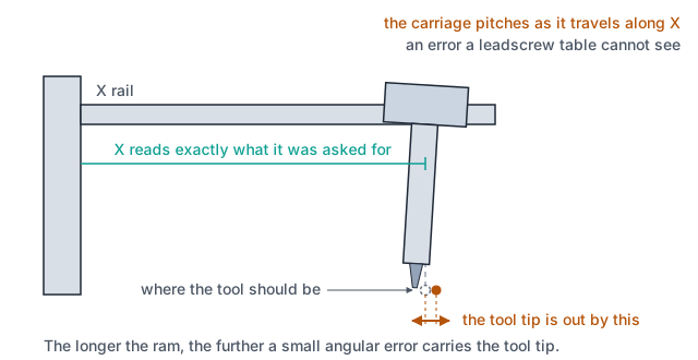
Position-dependent errors (PDGE) come from the per-axis maps. Each row of a map is a position and the six errors measured there: three displacements and three angular terms. This is what separates a volumetric map from a leadscrew table. The leadscrew table says “X is 12 µm short at 300”. The map also says how much X droops and how much it yaws at 300. Droop at the end of a long X carries the tool tip somewhere else entirely once Z is extended.
Position-independent errors (PIGE) are the ones that do not vary with position: squareness between the linear axes, and where each rotary axis actually sits and points.
From those, and the joint positions of a move, the model computes the error at the tool tip, the difference between where the tool actually is and where the machine was told to put it. The target is then moved by the same amount the other way.
Where it is applied
Section titled “Where it is applied”Late, on the planned path, and in one of two ways depending on the machine:
| Machine | How the correction is found |
|---|---|
| 3 linear axes | closed form: the error is evaluated at the nominal joints and subtracted from the target in a single pass |
| With rotary axes under a Cartesian solution | iteratively: the corrected target is solved through inverse kinematics, because moving the target also moves the joints the error was computed at |
It corrects the programmed path. Jog, homing and PLCopen motion do not run through the channel’s path planning, so they are not volumetrically corrected. Backlash and leadscrew compensation sit at the axis instead, and cover every kind of motion.
How a map is answered between measured points
Section titled “How a map is answered between measured points”A per-axis map is fitted, not interpolated point to point: a third-order polynomial per error component, dropping in order when there are too few points to support it: two points give a straight line, three a quadratic. With more points than the polynomial needs, the fit is least-squares, so the curve does not pass exactly through every measured point.
That is the opposite of a leadscrew table, which is piecewise-linear through every point. A leadscrew table is one axis’s own error and each point is trusted; a volumetric map is a machine model, where a smooth curve is closer to the physics than a chain of measurement noise.
Outside the measured range the value is held at the end point, with no extrapolation.
The three sets of numbers
Section titled “The three sets of numbers”On the channel, under Settings → Volumetric Compensation.
| Set | What it holds | Unit |
|---|---|---|
Axis Error Maps (PDGE) | one file per axis: position, then δx δy δz and εx εy εz | mm or ° for position, µm and µrad for the errors |
Geometric Errors (Squareness) | XY, YZ and XZ: how far the axes are from perpendicular | µrad |
Rotary Axis PIGE | per rotary axis: Location δx, δy, where the rotation centre actually is; Orientation α, β, how far the rotation axis is tilted | mm and µrad |
Squareness is the error that makes a square part come out as a parallelogram while every axis measures perfect on its own. The rotary terms are what a 5-axis machine lives or dies by: a rotation centre a tenth out of position moves the tool tip every time the table turns, and the error changes with the angle, so it looks like a program fault rather than a machine one.
Arming it gradually with the gain
Section titled “Arming it gradually with the gain”Compensation Gain scales the whole computed error before it is applied. At 100% the full
measured error is corrected; at 50% half of it is.
Bring a new map in below full gain, cut a test part, and raise it. A map with a sign error or a mis-set reference does not fail quietly at full gain. It moves the machine by the error instead of against it, doubling it.
A gain that is negative or not a number is treated as zero, so a mistyped value switches the correction off rather than inverting it.
The order to correct in
Section titled “The order to correct in”- Backlash, per axis
- Leadscrew, per axis
- Volumetric, over the whole machine
Each stage measures what the stage before it left behind. Measuring a volumetric map with the earlier corrections switched off and then running with them on corrects the same error twice, and the machine ends up worse than it started.
What it does not fix
Section titled “What it does not fix”- A part that is not clamped square. That is
G54.4, a per-part correction rather than a machine one. - Thermal growth. A map is a machine at one temperature.
- A loose machine. Compensation corrects what repeats. A joint with play measures differently every pass, and no map can carry a number that will not sit still.
Where to go next
Section titled “Where to go next”- Leadscrew Compensation: the per-axis stage that comes before this one.
- Axes & Channels: the kinematics these corrections are applied on top of.