Tool & Work Offsets
Bu içerik henüz dilinizde mevcut değil.
A program says X0 Y0 Z0. Two things decide where that actually is: where the part is
clamped and how far the tool sticks out. Both live on the OFFSET screen, one on
each tab.
Get either wrong and the program is still correct; the machine cuts in the wrong place.
The two tabs
Section titled “The two tabs”| Tab | Holds | Set it |
|---|---|---|
WORK | where the part datum is, per work coordinate system | every time you clamp a new part |
TOOL | how long each tool is and how wide it cuts | when a tool is fitted or reground |
Setting part zero
Section titled “Setting part zero”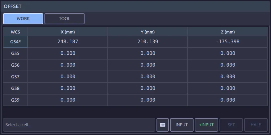
Pick the WCS row, G54 through G59, and the axis column. The star marks the one the
program is currently using. Then one of four ways:
| Key | Does | Use it when |
|---|---|---|
INPUT | writes what you typed into the cell | you already know the offset |
+INPUT | adds what you typed to what is there | you are nudging a datum that is nearly right |
SET | makes the current position read what you typed (blank means zero) | you have touched off on the surface |
HALF | halves the Work reading, putting zero midway | you have touched both sides and want the centre |
Touching off with an edge finder or a slip is SET: bring the tool onto the surface, type
the thickness you went through, or nothing at all for zero, and press SET. For a plain
zero where the tool stands, ZERO X ZERO Y ZERO Z on the
MANUAL screen do the same without leaving the jog keys.
+INPUT is the one to reach for after a trial cut: type 0.05, press +INPUT, and the
datum moves by five hundredths without you working out what the new absolute value should
be.
SET is the one you will use most. Touch the tool on the top of the part, type nothing,
press SET: Z now reads zero there. Touch a side and type the tool radius instead, and X
reads zero at the part edge.
The tool table
Section titled “The tool table”The TOOL tab is a table with one row per tool.
Each tool row carries four numbers:
| Column | Means | Unit |
|---|---|---|
Length | tool length as measured | mm |
ΔLength | correction on top of it, without touching the measurement | mm |
Radius | tool radius as measured | mm |
ΔRadius | correction on top of it | mm |
Geometry and wear are separate on purpose, and the reason is not really wear.
Geometry is what was measured, by the tool setter, a presetter, or by hand. Wear is what you decided after looking at the part. The measured length is not the length that makes the part come out right: spindle growth over a shift, tool deflection, setter calibration and the material springing back all sit in the gap between them. That gap is what wear holds.
Which is why re-measuring a tool does not wipe your correction. The measuring cycle refreshes the geometry and leaves the wear alone. Otherwise every automatic measurement would quietly undo the judgement that made the last part correct.
What the control uses is always geometry + wear: Length plus ΔLength, Radius
plus ΔRadius.
The TOOLS page and the tip angle
Section titled “The TOOLS page and the tip angle”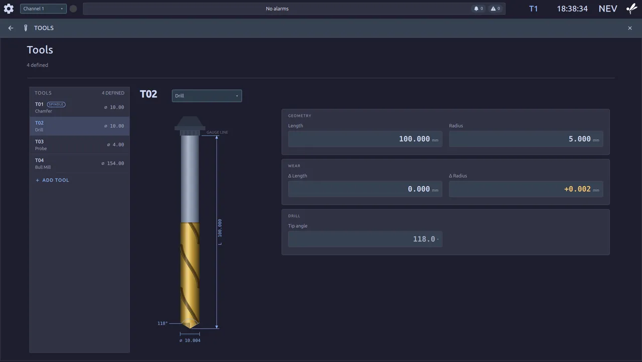
The TOOLS page shows the same numbers as cards, one tool at a time, with the tool drawn
from them. Tool 2 above is measured at 100.000 with a radius of 5.000 and a radius
correction of +0.002, so the drawing reads Ø 10.004: that is the diameter the control
cuts with. The SPINDLE badge in the list is the tool that is loaded.
For a drill, a centre drill, a chamfer mill or an engraver the last card has a Tip angle
field in degrees. It is the
cutter’s included point angle, and it is what a countersink’s depth is worked out from in
Cycle Programming: a COUNTERSINK step whose tool
has no tip angle shows set the tool's tip angle and cannot be compiled to a depth. Read it
off the tool’s drawing or measure it; a standard twist drill is 118.
For a bull mill the same card has a Corner radius field in millimetres: the rounding at the
rim of the flat end, as stamped on the cutter. The drawing, the 3D view and the part
simulation cut with it. Until it is entered the tool is drawn with a corner of 0.3 × its
radius and the value shows grey; a corner larger than the tool radius is drawn as the radius.
A star on the row number is the tool in the spindle. 02* means tool 2 is loaded, the
same marking the WORK tab uses for the active offset.
Tool length compensation: G43, G44, H
Section titled “Tool length compensation: G43, G44, H”H selects the tool row, and it is the tool number: H3 uses the row for tool 3.
| Code | Effect |
|---|---|
G43 H_ | apply the length, positive |
G44 H_ | apply the length, negative |
G49 or H0 | cancel |
The H must match the tool that is actually in the spindle. Nothing checks it: calling
H3 with tool 5 loaded runs the whole program at the wrong length, and the first plunge is
as deep as the difference between the two tools. The star on the tool table row tells you
what is loaded.
Compensation is modal, and it is cancelled by a reset along with the rest of the modal state.
D selects the radius the same way, for
cutter compensation.
A macro reads and writes tool length at #5081 onwards, and writes work offsets with
G10. See Custom Macros.
What this does not do
Section titled “What this does not do”- An edit does not reach the cut you are watching. The control reads offsets as it prepares each block, and it has already prepared a run of blocks ahead of the tool. A change lands somewhere further on, not on the pass in front of you. To correct a size, let the pass finish, edit, and run it again.
- Wear is not a substitute for measuring. If a part is out by a millimetre, the tool length is wrong, not worn.
Where to go next
Section titled “Where to go next”- Probing: letting the machine measure the datum instead of touching off by hand.
- Custom Macros: the rest of the offset and tool variables.